The design originally came from Beric Dunn, K6BEZ, and is centered around an AD9850 DDS module from eBay, supported by an Arduino Pro Micro and a bog-standard LCD display. Detailed info can be found on the Build Project Info page and in the builder forum.

The design is a simple SWR bridge using AA163 germanium diodes to read the forward and reflected power generated by the AD9850 board and the load under test. The Arduino ADCs read the sampled voltages across a sweep of frequencies and calculate the VSWR for the load. The user can select either the entire 1 - 30 MHz band for a sweep, or individual amateur bands, and is then presented with the frequency at which the SWR is lowest as well as the SWR reading itself.
Assembly was simple and quick. Thank God for kit designers who still make through-hole kits. Between my aging eyes and excessive coffee consumption, SMD kits are not a great idea for me. The folks at Rocket City 3D even designed and sold a 3D printed case for the project which not only looks great, but makes it less likely that I or the kids are going to static zap the project.


The final product is lightweight and easy to use. For a tool designed to locate the resonant point of a 50Ω antenna, this kit is great. For someone looking to map the performance of a load other than at 50Ω, this one isn't so hot out of the box.
Please, please, please don't misunderstand me: This kit is an excellent low cost tool, and more importantly, it's a great hacker platform, which you can see if you review the forums and see some of the adaptations. When trimming your dipoles to the right tune, this thing works great, right out of the box.
The difficulties I've experienced with the analyzer solely stem from my OCD engineer tendencies. These challenges are also part of why this kit is so much damned fun.
Problem: To the left or right of a 50Ω load, the analyzer does not correctly calculate the VSWR and there seem to be some frequency-dependent measurement offsets that shouldn't, in theory, exist in this simple design. When a load other than 50Ω is tested, the analyzer consistently calculates the SWR too low; as much as 50% low in some cases.
| Load (Ω) | SWR | |||
| nominal | measured | Calc. | measured | Error |
| 10Ω | 10.1Ω | 4.9505 | 2.5472 | 48.55% |
| 20Ω | 18.5Ω | 2.7027 | 1.6030 | 40.69% |
| 39Ω | 38.3Ω | 1.3055 | 1.0485 | 19.69% |
| 47Ω | 47Ω | 1.0638 | 1.0175 | 4.35% |
| 50Ω | 49.5Ω | 1.0101 | 1.0408 | 3.04% |
| 68Ω | 69Ω | 1.3800 | 1.0630 | 22.97% |
| 100Ω | 98.5Ω | 1.9700 | 1.2834 | 34.85% |
| 150Ω | 150.1Ω | 3.0020 | 1.7279 | 42.44% |
| 200Ω | 197Ω | 3.9400 | 2.1778 | 44.73% |
Where one would expect a 2:1 VSWR (100Ω), this instrument reports 1.729:1, and similarly up and down the range of resistive loads tested. Because this annoys me to no end, I'm trying to pin down some ability to automatically calibrate the instrument to make it behave better at other than 50Ω loads.
Idle Noise Compensation
The lowest hanging fruit, in my mind, is to make sure that the device is only measuring the energy from the AD9850 and not reacting to noise, either external or internal. In a system with no inputs, no voltages should be detected by the diodes or be sampled at the ADCs of the microcontroller. A simple routine can be inserted into the firmware of the analyzer that will very quickly read the detected voltages when no output is present from the AD950 DDS. The measured forward and reflected values in this routine can then be stored as an offset which can be subtracted from future measured FWD and REV voltages during a sweep of the antenna.
int FWD, REV;
int fwdOffset = 0; // idle noise on the FWD diode/amp
int revOffset = 0; // idle noise on the REV diode/amp

    // Average the REV/FWD voltages when unexcited
   setDDSFreq(0); // zero freq will turn off the DDS output
   for (int k = 0; k < 50; k++) {
      revOffset += analogRead(A0);
      fwdOffset += analogRead(A1);
    }

    fwdOffset /= 50;
    revOffset /= 50;
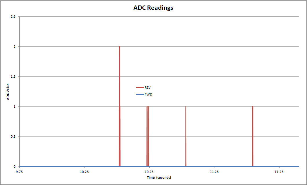
Here is what the idle noise looks like in terms of time on my system.
 |
| Uncompensated ADC values with zero DDS output |
Having determined the compensation factors above, we can apply them in code such as...
      // compensation applied at measurement time.
      REV = (analogRead(A0) - revOffset);
      FWD = (analogRead(A1) - fwdOffset);
...with the result that we see the idle measurements change to the below chart. Note the change in scale for the vertical axis. Across 3,000 measurement cycles, FWD remained solidly at zero, and REV showed departures from zero only seventeen times, none more than about 8 mV of transient noise. This is a reasonable measurement expectation for a SWR bridge with no RF input.
 |
| Compensated ADC values with zero DDS output |
So simple, so elegant, so automizable (a real word?), and so not any help for my problem. Next up, I'll look at compensating some mismatches in the amplifier gain and the detector diodes.
No comments:
Post a Comment